maintained by addie walti
 Version 3b - Nov 9, 2000
Version 3b - Nov 9, 2000
Here you find a collection of track- and pit lane commands. Commands do add functionality to track and pit lane. They do "belong" to track- or pit lane sectors. In a TE (trackeditor) select a track- or pit lane sector and You see the commands that do belong to it. We do refer to those cmds basically by their hexadecimal number 0x80 .. 0xee. They are listed along their number with more or less description of meaning and arguments. The library is not yet complete, but hopefully one day it will be.
You are all invited to verify, correct and/or extend the descriptions you find here. If you do, please prooved by examples, so i can verify it. And every idea of making this document more usuable is welcome !
If you look at the command library for the first time, you may want to have a look at the glossary first to get explanations on some "common" term. I would like to ask everybody to use those terms, so communication may become simplified.
As this is a growing document, you may want to watch the version number
at the top, and the revision history at the end of the file.
This document wouldnt be as complete as it is without many contributions of the following people (alphabetical order):
Frank Ahnert, Paul K Arnall, Marcel "babbel" Boorsbom, Dan Chinnapen, Bob Culver, Andrew Daley, Les "Fat Rat" Danyluk, Roland "Romeo" Ehnstrom, Paul Hoad, Michael 'NRG' Hompus, Vaino Iso-Hannula, Paul J. Josephson, Martijn Keizer, John K, Peter L Kessler, Brett Knuchel aka "Knuckels", Matti Laitinen, Graeme Nash, Obi Offiah, Robin de Paus, Nic "Swervin' Irvin'" Prins, Bob Pearson, Mal Ross, Dave S aka "SNQQPY.DOG", Oliver S. aka "Filou", Richard "dJomp" Selby, John Verheijen, "wire", Philip "Woody" Woodward, Adalberto Zapparoli and those people I possibly forgot to list (sorry in advance!)
Appendix
Glossary
LocationCodeTypeTables
Notes for Unk-Chasing
Revision History
0xa0 0xa1 0xa2
0xa3 0xa4 0xa5 0xa6
0xa7 0xa80xa9 0xaa
0xab
0xac 0xad
0xae0xaf
0xb0 0xb1 0xb20xb3
0xb4 0xb50xb6
0xb7 0xb8 0xb9
0xba 0xbb 0xbc0xbd
0xbe 0xbf
0xc0 0xc1 0xc2
0xc3 0xc4
0xc5 0xc6 0xc7
0xc8
0xc9 0xca
0xcb 0xcc
0xcd 0xce
0xcf
0xd0 0xd1 0xd20xd3
0xd4 0xd5
0xd6
0xd7 0xd8
0xd9
0xda 0xdb
0xdc
0xdd 0xde 0xdf
0xe0 0xe1 0xe2 0xe3 0xe4 0xe5 0xe6 0xe7 0xe80xe9 0xea 0xeb 0xec 0xed0xee
0x85 Track Width Change
0x86 Connect Pit Lane Start
0x87 Connect Pit Lane End
0x88 Pit Lane Cmd; Left Pits
0x89 Pit Lane Cmd; Right Pits
0x8a Track Markings Type A (not used in GP3)
0x8b Track Markings Type B (not used in GP3)
0x8c unk
0x8d unk
0x8e Left Kerbs Begin/Length
0x8f Right Kerbs Begin/Length
0x90 unk backwards
0x91 unk ahead
0x92 GP3: Horizon Base Texture Mapping; GP2: CC-Car
Coaching Space
0x93 unk (invalid cmd in GP3!)
0x94 CC-Car Coaching Left
0x95 CC-Car Coaching Right
0x96 Speed Limiter On
0x97 Speed Limiter Off
0x98 Left Fence Height Switch
0x99 Right Fence Height Switch
0x9a Define Custom Fence Height
0x9b Pit Lane Begin Offset
0x9c unk (different num of args in GP3!)
0x9d unk (invalid cmd in GP3!)
0x9e Pit Lane End Length
0x9f Pit Lane Fences Begin
0xa0 Pit Lane Fences End
0xa1 Pit Lane Entry; Join Right Pit Lane
Fence
0xa2 Pit Lane Entry; Join Left Pit Lane Fence
0xa3 Pit Lane Exit; Join Right Pit Lane Fence
0xa4 Pit Lane Exit; Join Left Pit Lane Fence
0xa5 unk
0xa6 unk
0xa7 unk
0xa8 Trigger Of Flag Men Waving At End Of Race
0xa9 unk
0xaa unk
0xab unk
0xac unk
0xad Track Banking
0xae 'Corrects' pit lines
0xaf Pair Of Swivel Arms
0xb0 Turn Ribbons/Banks Off (not used in GP3)
0xb1 unk
0xb2 Switch Borderlines On/Off
0xb3 unk (invalid cmd in GP3!)
0xb4 Track Width To Left
0xb5 Track Width To Right
0xb6 Pit Lane Start Angle
0xb7 Pit Lane Start Height
0xb8 GP2: Scenery Structure; GP3 unk
0xb9 GP2: Turn Ribbons/Banks On (invalid cmd in
GP3!)
0xba Insert Dummy Scenery Arm Pairs
0xbb GP2: Texture Mapping Light; (invalid cmd in
GP3!)
0xbc GP2: Texture Mapping; (invalid cmd in GP3!)
0xbd Light Source (Sun) Position
0xbe Extended View Distance Ahead
0xbf Extended View Distance Backwards
0xc0 Swivel Arm Left
0xc1 Swivel Arm Right
0xc2 Insert Dummy Scenery Arm Left
0xc3 Insert Dummy Scenery Arm Right
0xc4 Insert Dummy Scenery Arm Specified
0xc5 Define Far-View Section
0xc6 Far-View Window
0xc7 unk
0xc8 Default Texture Mapping
0xc9 Set Colors In GP2-Palette
0xca GP2: Kerb-Type A; GP3: Define Kerb Profile
0xcb GP2: Kerb-Type B; (not used in GP3)
0xcc Adjust Horizon
0xcd Adjust Shadow
0xce unk
0xcf Show Pit Objects Through Pit Fence
0xd0 Stabilize Scenery
0xd1 unk
0xd2 unk
0xd3 View Into Pit Lane Entrance
0xd4 View All Pit Lane From Entry
0xd5 View Into Pit Lane Exit
0xd6 View All Pit Lane From Exit
0xd7 Show Pit Scenery 1
0xd8 Show Pit Scenery 2
0xd9 GP2: Turn Obj-Ribbons/Banks On (not used in
GP3)
0xda ??? (un-sillied) (invalid cmd in GP3)
0xdb Switch Pits/Track Drawing Order
0xdc unk
0xdd Weirdo Enabler
0xde Black Flag Area Left
0xdf Black Flag Area Right
0xe0 GP2: Kerb-Type A Adjust; GP3: Place Shadow/Dry-Zone
0xe1 Fence Extension Off
0xe2 Fence Extension On
0xe3 unk
0xe4 unk
0xe5 Fence Extension Height Left
0xe6 Fence Extension Height Right
0xe7 unk
0xe8 Map Jip Onto Track Surface
0xe9 Texture Mapping
0xea Switch Ribbons On
0xeb Switch Ribbons Off
0xec Switch Obj-Ribbons On
0xed Switch Obj-Ribbons Off
0xee Scenery Structure
a1: Offset Into Sector
a2: Object Setting Offset
Objects (e.g. house, bridge, Advert etc) are defined in so called object shapes (formerly known as "internal objects"). In the trackfile You find a list of object settings (formerly known as object definition). In each of these object settings you specify which object shape you want to use, then you set up where and how it should show up relative to the track center line.
With cmd 0x80 You finally anchor the object by placing an object setting. In cmd 0x80 You refer to the object setting by giving its "offset" within the list. The TEs show this offset in the list of object settings.
So You can have the same object shape in different object settings (e.g. a pit building that can be seen from several sections from several angles in the track). And You can have the same object setting anchored at several positions along Your track (handy for e.g. adverts). But beware: in GP2 You cannot have more than one object settings anchored at the same position. This is also the case with "automatic road signs" (those you define by choosing them in a track or pit lane sector)
a1: Offset Into Sector
a2: View Distance from Position according to a1; valid range 60
- 255
The view distance in Granprix2/3 means how far away from the viewers position the track scenery and objects and everything still shows up. The view distance is strickly defined along the track and does not take care of the layout of the track. This means if the lanes are crossing (like e.g. in Suzuka) the other lane is not visible anyway, if the distance along the track is too big (as it is in Suzuka). On the other hand, the distance perpendular to the track does not matter. So the view range must not be imagined as a circle, as e.g. the PHTE implies !
The default view distance is about 60 track length units ahead and backwards. By the cmds 0x81, 0x82, 0xbe and 0xbf. You can increase this distance. But if You move on on the track the view distance decreases again until you are down at about 60 or until You increase the view distance. E.g. if you set the view distance to say 200, then move on some 50 units, then the actual view distance there is some 150 yet. Please think about this before going on. Its important to know how this works !
The cmds 0x81 and 0x82 are the old view distance commands. If you insert a cmd 0x81 or 0x82 and set a2 to a value smaller than 60, the view distance remains 60. If you set a2 greater then 60, the view distance for road and ribbons gets increased to the specified value. If you set a2=100 the view distance is 100 track-length units (but only for road and ribbons)
If you also want to extend the view distance for verges, fences and banks, you have to insert 0xbe and/or 0xbf instead.
And if you want to go beyond a range of 255 you may need to work with cmd 0xc5.
GP2: f1ct04 only; only once each in t50 and t65
GP3: f1ct06 only; only once at same place as above;
These cmds show up in Monaco only. There they seem to reverse the drawing sequence of (right side) ribbons and (left side) objects (maybe vice versa also) . In Monaco they prevent the Bridge-Object in the Portier-corner from bleeding through the right hand ribbons in the Loews-Hairpin. This constellation is special probably because the Bridge-object is positioned at the left side of the track, and so it bleeds through right side ribbons. Unfortunately i could not consistently reproduce ...
a1: Offset Into Sector
a2: Transition Length; typical values 4 .. 40
a3: New Width; typical values: 950 .. 1800
For detailed descriptions of the meaning of the cmd and the arguments please have a look at the cmds 0xb4 and 0xb5.
see pit lane guide for the details.
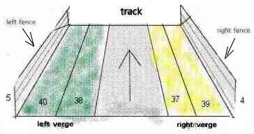
a1: Offset Into Sector
a2: Marking Type; typical values: 3 (gives yellow color) 8 (light grey)
8968 14088 49160
a3: Number of markings; (determins also length of marking); typical
values: 2 3 4 5 6 8 13
a4: DFC (distance from center of track); same unit as track width (see
e.g. 0xb4)
a5: Angle Of Line; typical values: -620 0 620
a6: Marking Type 2; typical values: 257 513 771 1281
the values of a3 a4 a5 and a6 depend on the value of a2. they are all the same most of the time. a4 sometimes also depends on track widths. For valid values you may want to have a look at those of the original tracks.
When used for starting-grid, for the a1-values we have a "base-offset to s/f" of 42, which means we have to insert the three appropriate cmds in a tracksector that has a distance of at least 42 units back from the end of the track. If its exactly 42, we have to set the offsets in the three cmds to 41, 0 and 2 (or 41, 2, 0).
With pit lane parking markings, for the a1-values we have a"base-offset to pit lane code" of 2, which means we have to insert the four appropriate cmds in a pitlanesector that has a distance of at least 2 units back from the pitlanesector including the "pit lane code"-cmd. If its exactly 2, we have to set the offsets in the four cmds to 0, 3, 1 and 4.
These descriptions are maybe a bit brief, but you will know what i mean, when working with a starting grid, respectively pit lane markings.
It looks like the same type can either be inserted in the track OR in the pit lane.
a1 : Unused
a2 : Offset Into Sector
a3 : Length Of Kerb
These cmds are used to set the immediate start position and the length of a kerb in a track or pit lane section. Basically kerbs have to be enabled in the track or pit lane sector by checking the appropriate checkbox in the track sector dialog box (where You set length and angles etc.)
As soon as all track sectors have their checkboxes checked, and kerb type selected, You can specify the kerb with one of these cmds. If length is greater than the tracksector, the kerb-checkboxes in the next sector also have to be checked.
There are several types of kerbs, A and B in GP2 and A and B for left and right side each in GP3.
see cmds 0xca and 0xcb for defining the shape of those kerb types.
Robin de Paus:
"When setting a 0x8e or 0x8f command, this command applies to the rest
of the track, or until another 0x8e or 0x8f command is found (not just
one kerb).
Kerb Type A:
* A kerb of this type can be only one segment long.
* When the segment is curved, it will go from the start of the track
to the end of the track.
* When the segment is straight, it will follow the rules of the 0x8e
(or 0x8f) command; it will start at the a2 value and runs until the a3
value OR the end of the track-segment when a2+a3 is bigger than the length
of the segment.
* When the a2 value is bigger then the length of the segment the kerb
will not show up at all (of course unless the segment is curved).
Kerb Type B:
* A kerb of this type always follows the 0x8e/f command.
When you apply a kerb before a 0x8e or 0x8f command is given, GP2 will
use a 'default' command with a2=1 and a3=12."
a1: ?Offset Into Sector; typical values: 2 6 14 15 90 (GP2: f1ct09
t15)
a2: unk; typical values: 10 12 22 26 29 30 58 150
Pretty vague. In original tracks you often find this cmd before "dangerous" corners or hairpins. After tests with the notorious first corner of Bern-Bremgarten I came to the conclusion, this cmd could make the cc-cars to keep more distance to each other ! It could be e.g. viewed in the hairpin of adelaide and in mirabeau of monaco.
Wøødy :
a1: always 0
a2: position of horizon section (typical values 0 to 14)
a3: jam texture id
The horizons split into different pieces, 2 vertically and typically 14-ish surrounding the track horizontally. The lower jams are smaller than the upper horizons - with this cmd you can alter the texture of the lower ones.
Its sort of a new fix for the no-mans land under the horizon, looks pretty messy w/ them all removed.
If you'd like to check delete them all in any track, or change all of the arg 3 values to a distinctive texture id. I can't guess why these are treated so differently from the upper horizon w/ 0xcc, other than its a new cmd for gp3?
Still pretty vague. They seem to influence the cc-cars. When looking at the original tracks you notice the value for the outside of the corner is usually small (1 or 2), for the inside of the corner, the value is greater (4 or 8). So we could say the value is similar to the theoretical space between cc-line and border of the track. Or maybe better "the safe space" along the cc-line.
I made tests with the notorious first corner of Bern-Bremgarten, where normaly chaos happens after a start of a race. Maybe its a coincidence, but after setting both values to 1 before the corner the number of accidents decreased significantly, although i could not really recognize different behaviour of the cc-cars. Maybe they have become somehow more careful or at least less fragile !?
With these two cmds you define the speed limited zone in the pit lane. see pit lane guide for the details.
note: "speed limiter on"-cmd must not be in the same pit lane sector as "pit lane fences begin" cmd 0x9f. else gp3 may crash back to desktop at loading the track.
a1: not used
a2: Height Code; values 1 .. 8; then starting again (9 is same as
1, etc.; 0 same as 8)
With these cmds You can switch between 8 height values. For setting those height values please refer to cmd 0x9a
The new height value will be set at the beginning of the track or pit lane sector including one of these cmds. The whole preceding sector will feature a transition height from the old to the new fence height.
Looking once again at the cmds 0x98/99 we also can say it like this: a2 is simply a index to a table of height values: 1=200; 2=400; 3=600; 4=800; 5=1000; 6=1200; 7=1400; 8=1600; 9=200 (again); etc.
As found by Filou, cmd 0x9a lets you specify a custom value for one of those standard height values. By e.g. inserting a 0x9a with a2=2 and a3=1800 the inserting of a 0x98 with a2=2 does not give a height of 400 anymore, but a height of 1800.
If you want to change a left fence standard height then you refer to the table with the indices 1 .. 8. If you want to change a right fence standard height, then you refer to the table with the indices 9 .. 16. So if you want to repeat our example with the right fence you insert a cmd 0x9a with a2=10 and a3= 1800.
If you define a new height value with 0x9a, this value is changed globally. Even in the pit lane. You also can insert the 0x9a in the pit lane and it counts for the track also.
a1: Offset Into Sector; (offset of visible pit lane begin)
In GP2.exe there seem to exist a slot-specific value that defines how far away from THE VISIBLE pit lane-beginning, the cc-cars start their pit lane-approach.
see also pit lane guide
a1: unk
a2: unk
a3: unk
a4: unk
a5: unk
a6: unk
a7: unk
a1: Length of visible rest of pit lane
The value of a1 has to be smaller at least by 2 than the rest of the pit lane. Smaller by 1 and greater gives you gfx-bugs. If the value equals the rest of the pit lane, the track hangs gp2.exe. Sometimes gp2.exe also hangs when the value is greater.
But even if the visible part of the pit lanes ends before the actual end of it, the computer cars do not go onto the racing line until the actual end.
see also pit lane guide.
see also pit lane guide.
see also pit lane guide.
These four cmds are used to connect track fence and pit lane fence. You always connect the BEGINNINGS of the fences. 0xa1 and 0xa2 in the track are the "counterparts" of the 0x9f in the pit lane. 0xa3 and 0xa4 in the track are the "counterparts" of the 0xa0 in the pit lane.
see also pit lane guide.
a1: ?Offset Into Sector; always 0 in the original tracks
GP3: here not every track includes one of these ?!?!
a1: unk; always 0 in the original tracks
a2: unk; typical values: 6 19 20 26 39 70
a3: unk; typical values: 0 or 7
a4: unk; typical values: 6656 11264 12800
not used in original tracks of GP3.
a1: always 0 in the original tracks
a2: always 18 or 15 in the original tracks (always two of them, one
with a2=18 and one with a2=15)
a3: unk; typical values: 14 15 20 21 23 24 25 27 29 31 32 36
a4: unk; typical values: 25 26 27 29 31 32 34 36 37 38 40 42
a5: unk; typical values: 4 9 10 13 14 17 20 26 27 28 30 32 33
PH: this cmd sometimes appears in t0 of the track file. because of the structure of the track file it follows directly after the "Untextured Kerb Colors". Looking at the cmds arguments i'm wondering also if the cmd 0xac might not also be a coloring cmd ?
But in GP3 its included !
a1: ?unused
a2: Transition Length (of rising/lowering bank)
a3: Amount Of The Banking; + is for left banking, -ve for right
banking.
You'll have to insert two commands in two different sectors.
First one to get the banking to begin. (i.e. Length: 10, Height: -1000).
Then another where you want to end it again. (i.e. Length: 10, Height 0)
dJomp: This command seems to move the yellow pit lines to the side of the track, so the whole line is visible.
a1: ?unk (Always 0?)
a2: Location: 16384: right; -32767: left; -16384; both lines
a1: Offset Into Sector (for the 0xaf/0xb8 or 0xaf/0xee pair)
a2: Angle Of Left Arm; (useful: negative value); -16384 (90°
to the left)
a3: Angle Of Right Arm; (useful: positive value); e.g. 16384 18432
20480 24576
In a single track-sector there can also be several pairs of 0xaf/0xb8 (0xaf/0xee respectively) with different offsets in cmd 0xaf.
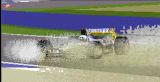
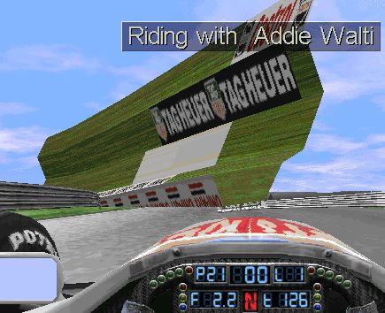
See the following pictures for an example. All three screenshots feature exactly the same clip of a certain part of a track. The view is perpendular to the track to the right side. There are three "arms" visible. One at the left side of the picture, one at the right side and one in the middle. The only difference in the three images is the angle value of the middle "arm".
In the top image the value is 16384 (its a right arm; left arm would be -16384). The value in the middle image is 20384. The value in the bottom image is 12384.
(af.jpg) 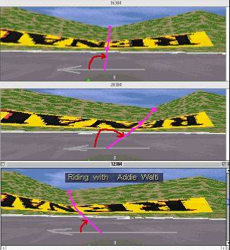
The appropriate sketch:
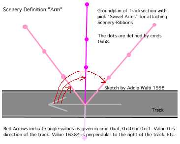
for more details on the angle value, see compass chapter in glossary.
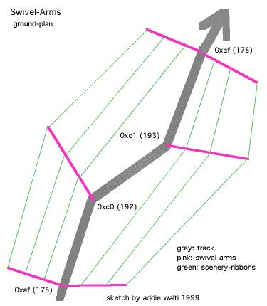
There are also the cmds 0xc0) and 0xc1. They act basically the same as cmd 0xaf but they define just a single swivel arm. see following sketch:
In GP3 not used anymore, possibly replaced by one of the cmds 0xa - 0xed.
a1: Offset Into Sector
a2: Location Code Type B
Default: Ribbons/Banks off
For switching them on in GP2, use 0xb9 or 0xd9.
Do ONLY insert this cmd at the same position (tracksector AND offset) as a 0xaf/0xb8, 0xc0/0xb8 or 0xc1/0xb8 pair. (see original tracks for reference). NEVER have it alone. If you do, gfx bugs of the strange kind may happen.
GP2:
a1: unk
a2: switch (only first 2 bits used)
set bit 1 to turn off left boundary line.
set bit 2 to turn off right boundary line.
This means that value
0 has no effect,
1 turns left line off,
2 turns right line off and
3 turns both lines off.
It works global only!
woody: GP2: It seems to displace the wall texture right to the trackside even in front of any kerbs, but the collision detection remains where it is set to (ie verge width). It automatically turns off verges and banks, but not ribbons. The args are:
a1 = always zero? (NOT offset, NOT wall texture separation, NOT window
length)
a2 = trackside to affect
(-32767 = left side
16384 = right side
-16384 = both sides
0 = return to normal)
It is not global - inserting another 0xb3 overides the first but not before that point, so can be switched around without limits over the lap
Well it makes quite a mess so I'm thinking, what usefulness, not in any original tracks but characteristics seem to parallel with what you see sometimes with (a) pit fence connections (b) cc-cars overiding fences, maybe something to do w/ GP1 though, works in pitlane so maybe some use there
a1: unused (no effect)
a2: Transition Length; typical values: 2 ..13;
a3: New Width; typical values: 880 (narrow) .. 1300 (regular) ..
3800 (la source spa)
With these two cmds You can change the track width on one side of the (imagined) centerline. Cmd 0x85 is kind of combination of 0xb4 and 0xb5. See the following images for getting an idea how it works:
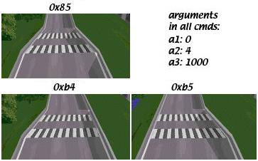
Its three times the very same section in a track. The first crosswalk marks the beginning of the tracksector including the track width change cmd. The "Length" of the crosswalks are 1 each. The width before the change is 1800 on both sides.
It does not matter what value is set in a1, the change of width always starts at the beginning of the sector including the track width change cmd. Transition is not limited to the starting sector, its possible over several sectors.
If You have small figures for the track-width this also affects the verge width.
The inital (symmetrical) track width is set in the track config section, though the PHTE does not show it. But the IHTE does.
For detailed calculations of track and verge width, see formulas of
Robin de Paus in the Appendix.
Pit Lane Width
Default pit lane width seems to be 640. You can change the pit lane width the same way as the track width. e.g. inserting a cmd 0x85 in p0 with offset 0 and transition length 0 to have immediately the new width. But as the pit lane ends are attached to the track in a special way, you will notice an undesired effect. The centerline of the pit lane seems to be connected to the track at a lateral distance of 640 off the appropriate track side, independant from track width! So changing the pit lane width with cmd 0x85 will shift the yellow (pit lane) borderline away from the white (track) borderline. But cmd 0xb4/b5 will do the job perfectly. If you have right side pits, use cmd 0xb4 [sic!], et vice versa.
When checking out this subject you also may want to keep your eyes on the cmds 0x9b at the entrance and the cmd 0x9e at the exit and the general pit lane layout problems.
a1: not used
a2: pitlane start angle
Vaino: (for GP2) I tried this command first at track (t01) and then at first sector in pitlane (p00). There were no visible difference. I found that positive low values turn pitlane start angle to left and negative to right. My pit was on the right side.
I found that if used values above +/- 300 angle was decreasing! I haven't yet tried this with "real" track. I tried it with my test track and when pitlane start angle was changed GP2-engine twists track so that end of pitlane connects to the track.
That's what I know up to now.
Wøødÿ (harassing my charset :)
cmd 0xb6 (offseting pitlane at an angle without using curved pit sections) - in the command library it says after a value |300| the angle starts to decrease again, have to say I don't think this is correct, I find the EFFECT decreases but not the absolute value, so I'd guess a multiple of an n'th root somewhere; but command is dodgy after about 30 degrees - causes horrible distortion of pitwalls, so useful units 0 to 600 = about 0 to pi/4 but with weird progression
a1: not used (?)
a2: pitlane start height (gradient)
Vaino: (for GP2) This height value is very strong. Value 10 gives about 20 degrees. I don't know more yet. Maybe this cmd is used to somehow compensate effects of banking ?!
For GP3 the scenery structure functionality is moved to cmd 0xee.
Now a description of the functionality in GP2:
Command to define the scenery structure. The "scenery" consists of bank-left, bank-right and four ribbons. Whether the ribbons are on the left or the right side can be set up.
a1: unk; ?always 0
a2: valid values 0..4 basically it gives the location of the track
within the 4 ribbons. You can also refer to it as "the number of ribbons
to the right of the track"
a3 .. a14: coordinates of ribbons, as can be seen in the sketches
Origin of x- and z-coordinate is the middle of the track (if You have symmetrical widths).
This is the famous scenery-ribbon-cmd. It defines the basic scenery, together with the swivel-arm-cmds 0xaf, 0xc0 or 0xc1. You have them allover the track and alltogether they define the shape of hills, forests, meadows, dunes, whatever. The maximum number of cmds 0xb8 seem to be 128. If you insert another one, the very last of them in the track gets lost.
As mentioned you never see the cmd 0xb8 standing alone, there always is another cmd BEFORE it, a cmd 0xaf, a cmd 0xc0 or cmd 0xc1. The latters do define the position and some angles, and 0xb8 defines the structure of the scenery.
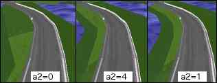
It is important you understand the meaning of argument a2 "ribbons to
the right". With this argument you adjust on which side of the road you
want the four ribbons. The banks always remain on their given side, but
the ribbons can change their side. Normally you may have 2 on each side.
If you want 3 on the right side you set a2 to 3 and the most left ribbon
becomes the most right one.
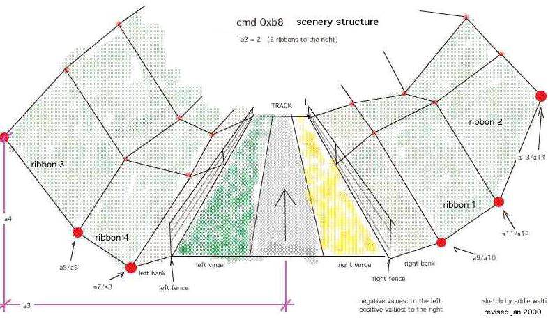
(b8_bas2.jpg)
But beware, the labeling of the coordinate-pairs is only valid, if you have a2=2. Whatever number of ribbons you have on each side, the labeling of the coordinate-pairs always goes from left to right. So if you e.g. have all ribbons on the left side (a2=0) then a9/a10 of the image above becomes a13/a14. The numbering of the ribbons start at the right side, right after the bank. After the last ribbon to the right it switches to the very left ribbon.
See also Scenery Tutorial of Martijn Keizer.
(see also GP2: 0xb0 and 0xd9)
martijn: "With this cmd you can "turn on" individual ribbons and/or banks depending on the value in argument a2. The ribbons are showing up no matter what detail level is set in the game (in opposite to 0xd9)"
a1: Offset Into Sector
a2: Location Code Type B
Do ONLY insert this cmd at the same position as a 0xaf/0xb8, 0xc0/0xb8 or 0xc1/0xb8 pair. (see original tracks for reference). See 0xb0 for an example of a gfx-bug that can happen when not following this rule.
To switch them off again, use 0xb0
Default: Ribbons/Banks off
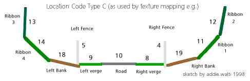
a1: Offset Into Sector; typical values: 0 2 3
a2: Location Code Type C; (location of texture);
typical values:5 9 14
a3: Length; (of the mapping-area, follows the direction of the ribbon);
typical values: 10 14 40 63
a4: Texture ID; typical values: 33 160 198
a5: Repeats; (within length of the texture; repetition horizontal);
typical values: 1 4 5; preferably a rounded proportion of the length;
But it's not easy to see why this command exists, see also 0xbc ...
With this cmd we do define an area, where a texture gets mapped. First we define the size of the area, 2nd we select the texture and define how it gets mapped on the definend area. We define repetition horizontal and vertical, rotation.
a1: Offset Into Sector
a2: Location Code Type C; (location
of texture)
a3: Length; (of the mapping-area, follows the direction of the ribbon)
a4: Texture ID
a5: Repeats; (within length of the texture; repetition horizontal);preferably
a rounded proportion of the length;
a6: Vertical Resolution; (16 is full texture)
a7: Vertical Shift; (within the texture)
if this shift is somewhat greater than 0 and less than the vertical
resolution of the texture, then the texture gets shifted upwards by this
amount. that means the upper margin gets cutted and pasted at the lower
margin.
a8: Rotation; (of the texture in steps of 90degrees.
value 0-15 : 0 degrees
value 16-31: 90 degrees
value 32-47 : 180 degrees
value 48-63: 270 degrees
common rotation values (to avoid distortions) : 3 (0 degrees), 19 (90 degrees), 35 (...), 51, 67, etc.).
a6 and a7 could be used if You want to use only part of a texture.
There is a limit for the number of cmds 0xbc in a track. 221 cmds work, but more could fail.
a1: unk; ?always 0 (ever?)
a2: Direction; (0..65535? means 0..360 degrees)
a3: Angle of Sun Above Horizon; typical values: 7000 .. 12500
PLK: "a2 is definitely a rotational value. The sun in Portugal has a value of -3640. In the track I'm working on now, objects which face me while I exit the pits where in deep shadow. I changed the value to -18640, and the sunlight had turned around (anti-clockwise) to light up these objects."
a1: Offset Into Sector
a2: Location Code Type E
a3: View Range from Position according to a1; valid range 60
- 255
For a brief introduction to the subject "View Distance" please have a look at the old view distance cmds 0x81 and 0x82.
If you insert a cmd 0xbe or 0xbf and set a3 to a value smaller than 60, the view distance remains about 60. If you set a3 greater then 60, the view distance gets increased to the specified value. If you set a3=100 the view-distance is 100 track-length units. In opposite to the old view distance cmds 0x81 and 0x82 you can define what should show up in the extended view distance. With a2 you can do this.
Road and ribbons show up always. With a2 you can also enable the other locations. So if you e.g. set a2=19 the following locations show up: road, ribbons, verges and left bank.
It looks to me like you only need these two cmds to set the view distances. But in the original tracks these cmds are always inserted together with a cmd 0x81 or 0x82. IF they are inserted as a pair ALWAYS the view-distance is set by the old cmd 0x81 or 0x82 and the location is set by the new cmd 0xbe or 0xbf. This means a3 of 0xbe gets overridden by a2 of 0x81 and a3 of 0xbf gets overridden by a2 of 0x82.
If you want to go beyond a range of 255 you may need to work with cmd 0xc5.
a1: Offset Into Sector
a2: Angle Of Arm; (0xc0: useful: negative value; 0xc1: useful:
positive value)
The x- and z- coordinates of the scenery-ribbons are defined in the cmd 0xb8.
a1: Offset Into Sector
a2: Dummy scenery arm spacing (horizontally); typical values: 0, 1,
2, 3, 4 etc
a3: Dummy scenery arm spacing (vertically); typical values: 0, 1, 2,
3, 4 etc
(0xc4: a4: Location Code Type B (B2 GP2; B3
GP3); specify ribbons to attach)
paragraph by woody:
Using one of these four cmds automatically inserts dummy scenery arms up until the next real swivel arm cmd (pairs of 0xaf/0xee, 0xc0/0xee or 0xc1/0xee). Args a2 and a3 define the spacing of the dummy scenery arms, and arg a4 dictates which ribbons are pinned to them. The smaller the values of a2 & a3, the smaller their spacing and so the better the ribbons follow the layout of the track. However a value of zero does not space out the scenery arms at all, and so there is either no effect or a previous effect is switched off in that plane.
Without 0xc2-c4 or 0xba the ribbons go straight from one swivel arm
to the next, causing a mess around corners or up & down hills.
The cmds 0xc2, 0xc3, 0xc4 and 0xba all call the same function. The
only difference is a4, which is hardcoded differently in all cmds except
0xc4 in which it can be specified.
With cmd 0xc2 all the ribbons on the left side of the track are affected;
with 0xc3 all the ribbons on the right side and with 0xba all the ribbons
on both sides of the track.
These dummy arms are strange in that it seems you can choose to attach
a ribbon's DFC value but not its Z value & vice versa. Also they are
not "swivel" arms because their angle cannot be adjusted, hence named scenery
arms. And with cmd 0xc4 some ribbons can be attached and others not.
The track length to affect is defined by the distance to the next real
swivel arm(s) minus the offset in a1. The number of dummy arms inserted
is defined by their spacing.
The shape of the scenery structure as set by 0xee is averaged equally
between the two real swivel arm cmds; it's unaffected by these four cmds.
On this images you see the meaning of "continue scenery" on the left
side of the road. With a2=0 the effect is switched of with a2=1 its maximized.
(dont get confused by different shades of green. its only shadows)
a1: Offset Into Sector;
a2: Begin Far-View Section; DFS (distance from s/f)
a3: End Far-View Section; DFS (distance from s/f)
a4: Location Code Type D [thanks to dan];
defines what parts of scenery is visible
a5: unk; always 0 in the original tracks
a6: unk; always 0 in the original tracks
a7: unk; always 0 in the original tracks
(a8: Periferal Angle [thanks to dan!]; typical values: 0 1024
3072 5120 14336 -512);
In some tracks cmd 0xc5 features 7 args in other 8 args. This is set by a switch in the track config section. See c5c6 guide for the details how to change this switch.
With 0xc5 you define what part of the track should show up in the distance. And with 0xc6 you define in what part of the track this section should show up.
see also 0xd0
a1: ?unused
a2: Location Code Type C
a3: Length Of Repeated Section
a4: Texture ID
a5: Repeats; (within Length of the texture; repetition horizontal);
usually 1
a6: Vertical Resolution
a7: ?Vertical Shift; (within the texture)
a8: Rotation; (of the texture; in steps of 90degrees; common values:
3 (0 degrees), 19 (90 degrees), 35 (...), 51, 67, etc.).
With this cmd you set a default texture on a location according to a2.
(c9_ex.jpg; click to enlarge) 
(this screenshot you find also in the mentioned tutorial)
The arguments of the cmd 0xc9 are:
a1: ?unused
a2: Palette index 1
a3: Palette index 2
a4: Hue angle 1
a5: Hue angle 2
a6: Saturation 1
a7: Saturation 2
a8: Brightness 1
a9: Brightness 2
GP2:
a1: ?unused
a2: Distance to Height1
a3: Distance to Height2
a4: Height1
a5: Height2
GP3:
a1: ?unused
a2: Selektor (Vaino: 0=left A, 1=right A, 2=left B, 3=right B)
a3: Distance to Height1
a4: Distance to Height2
a5: unk (?always 800)
a6: Height1
a7: Height2
Please have a look at the following sketch. It features a cross-section
of a kerb at the right border of the track.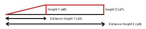
(Sketch by John Verheijen)
a1: ?unused
a2: Rotating scenery (similar to track start angle); valid values
0..65535
a3: Horizon height; valid values 0 .. 32767 (higher values give
0 height; default: 600-650)
Low values make horizon smaller, high values bigger. If used 0, there is no horizon. And 1280 (or near) dublicates the size of horizon."
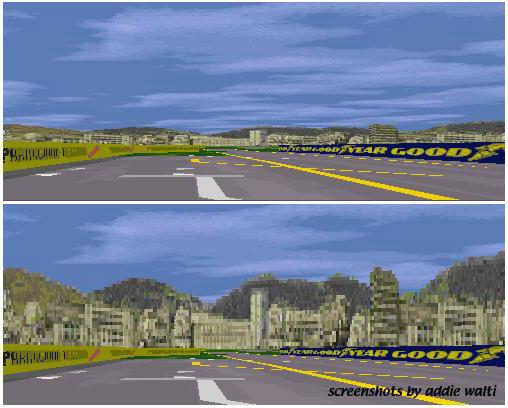
(upper with a2 = 0, a3 =640; lower a2 =0, a3 =2400)
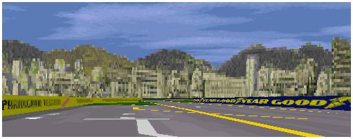
(a2 =2048, a3 = 2400)
It works global only!
a1: Offset Into Sector
a2: Location Code Type A
a3: Range of effect
a4: Light Up Or Darken Factor; 0 (dark) .. 15 (bright).
Example in original GP2 Monaco t22-t24
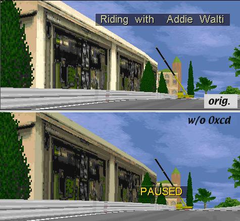
Upper: with 0xcd in t22
Lower: w/o 0xcd in t22; the windows of the massenet hotel are darker
In this example the cmd 0xcd is used to lighten up the frontwindows of the Hotel Massenet. Or in technically terms: to lighten up the texture on ribbon 4.
GP2: only once used in f1ct04 t68 (tunnel)
a1: unk; typical values: 0
a2: unk; typical values: 4
SNQQPY.DOG: "It occurs only once in f1ct04.dat, Monaco. It appears in t68, the sector just before the tunnel. Its argument is (4). Removing it caused the tunnel roof section bleed through the right building wall as seen from portier corner."
SNQQPY.DOG: "It always appears in track sectors before the start of the pits. Usually at some distance. However the second argument always covers the whole of the track upto or just beyond where the pit fences begin. My conclusion is therefore to allow the pit building and pit objects to be seen at a distance through the pit fences but not through the track fences.
There are two arguments to this cmd. The first i believe is the offset from the position of the track where its located. The second marks the distance at which the cmd has an effect, and i believe in theory could run for as long as the track.
Its use appears to be to allow objects to be seen through or across fences. Aside from this observations it would appear as a bug if used in the wrong place."
With this cmd you can stabilize scenery. Typical instabilities result in flashing and shifting/warping of textures on fences, banks and ribbons. First you have to identify the part of the scenery that is to stabilize. Typically its an area between two swivel arms (banks, ribbons) or within a tracksector (fences etc.).
Say you have a flashing texture on the left bank between two swivel arms. Now you can try to stabilize it with 0xd0 located between the two swivel arms. You may want to start with a single 0xd0 in the middle between the two arms. If it does not yet workout, you may want to insert more of them with smaller gabs between them.
E.g. i had a flashing texture at the left bank between two swivel arms with a gap of 5 track length units between them. I inserted 4 cmds 0xd0 with a1=1, 2, 3, 4 and a2=0 and a3=2048. No more flashing :)
Shifting of textures is a bit more subtle. You can see it best e.g. in forests. When driving through a forest, sometimes you see the trees-textures shifting away from you and then back again.
0xc2, 0xc3 and 0xc7 seem to be somehow related to 0xd0.
a1: unk; typical values: 2 6 10
a2: unk; typical values: 132 140 145 155
see also 0xdd !
By the help of this cmd, the pit lane entrance becomes visible if you
have not yet entered the pit lane.
As soon as you have entered the pit lane it becomes visible anyway,
but as long as you are outside, visibility (view distance) depends on a2
of this cmd.
The pitcrews do not get visible.
For further descriptions see pit lane guide
This cmd works similar to cmd 0xd3, but with unlimited view distance. As soon as you pass this cmd, all pit lane is visible from the track. f1ct12 (monza) is the only original track where you see from the entry "through" the pitlane to the exit. Thats why this cmd is used but there.
If you use this cmd at the entrance, you also have to use cmd 0xd6 at the exit, et vice versa.
You may experience gfx-trouble (e.g. pit lane armco bleeding in regular track) if you use these cmds in pit lanes that are not all-straight.
By the help of this cmd, the pit lane exit becomes visible if you look into the pit lane from the wrong end and have not yet entered it. As soon as you have entered the pit lane it becomes visible anyway, but as long as you are outside, visibility (view distance) depends on a2 of this cmd.
The pitcrews do not become visible.
For further descriptions see pit lane tutorial.
This cmd works similar to cmd 0xd5, but with unlimited view distance. As soon as you pass this cmd, all pit lane is visible. f1ct12 (Monza) is the only original track where you see from the exit "through" the pitlane to the entry. Thats why this cmd is used but there. If you use this cmd at the exit, you probably also have to use cmd 0xd4 at the entrance, et vice versa.
You may experience gfx-trouble (e.g. pit lane armco bleeding in regular track) if you use these cmds in pit lanes that are not all-straight.
It sets up the visibility of the pit lane entrance,
Paul Hoad: "it simply stores the position of the sector in which
it appears which might mean that it may be trigger for something."
Maybe this spa screenshots give some hint:
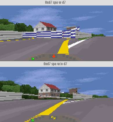
To me it looks like it sets up the drawing order in a specific way.
See also 0xdb
a1: Effect-Distance
This cmd enables the view into the pit lane from the track accoring
to the setting of the 0xd3 cmd on a distance given by a1. If 0xd8 (216)
is missing you see into the pit lane through the pit entrance. As soon
as the entrance is passed, the pit scenery disapprears. But if you insert
a 0xd8 it does NOT disappear !
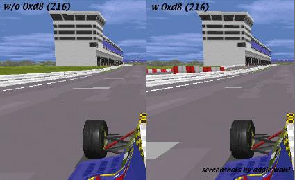
Typically you insert a 0xd8 in the track at about the pit entrance, where the "two worlds" are connected. As a1 you enter the distance of the effect. Beware the distance has to be smaller than the remaining section of the track until the s/f line. If the remaining section is 40, like in original interlagos f1ct01.dat, the maximum a1 is 39, else the pit lane scenery wont show up at all.
The length of pit lane showing up is given by a2 of 0xd3. In the following examples i took original Interlagos f1ct01.dat, set a1 of 0xd8 in t96 to 39 (max possible value). This gave me the the left screenshot in the following image:
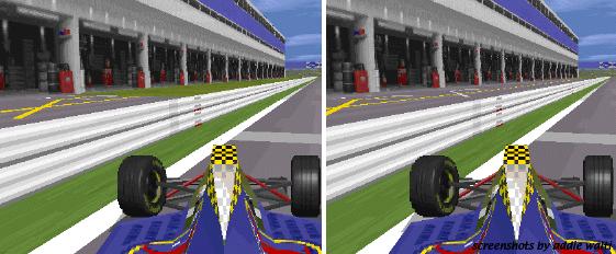
(In original interlagos a2 of 0xd3 in t88 is set to 42). After that i set a2 of 0xd3 in t88 to 72 and got the right screenshot in the image above.
The pit lane scenery was only visible in front view. When driving in the wrong direction the pitlane scenery wasnt visible anymore.
Seems not to work in far-sight (see 0xc5)
In GP3 not used anymore, probably replaced by one of the cmds 0xea - 0xed.
If you want them showing up no matter what detail level is set, you have to use 0xb9 instead"
a1: Offset Into Sector
a2: Location Code Type B
Do ONLY insert this cmd at the same position as a 0xaf/0xb8, 0xc0/0xb8 or 0xc1/0xb8 pair. (see original tracks for reference). See 0xb0 for an example of a gfx-bug that can happen when not following this rule.
To switch them off again, use 0xb0
Default: Ribbons/Banks off
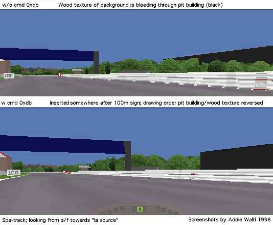
a1: Offset Into Sector; typical values: 0 1 3 4 9 20 54 99 (see f1cts
11 12)
a2: Location Code Type B; typical values:
1 2 4 6 8 10
Cmd 0xdb defines the sequence of drawing track- and pit lane scenery gfx. This cmd can be found (only) in the original Spa-track f1ct11.dat in t0. In spa you have a hairpin immediately following the s/f straight and after that another straight (towards eau rouge). Enclosed in these two straights there is the pit lane, the pit building in particular. It seems like the gp2.exe normally draws first the pitlane scenery, then the regular track scenery (covering appropriate part of pitlane scenery and objects). So in our case the trees of the right side of the straight after the hairpin would become pasted over the pit building. but here comes 0xdb.
Cmd 0xdb seems to tell the gp2.exe to switch the sequence of drawing there. its parameter seems to be (once more) an offset into the sector. So with a cmd 0xdb, the gp2.exe first draws the regular track scenery beyond 0xdb, then the pit lane scenery, then at last the track where you are standing, if you are standing before the cmd 0xdb.
You can check this easily by removing the cmd 0xdb in the original Spa-track
and then have a look at the pit building, standing in the middle between
s/f line and hairpin.
another effect can be seen, when looking from the track into the pit
exit ...
but here it needs some more experiments (any volunteer?)
summary:
you just need the 0xdb when you have a layout of track and pit lane
similar to spa. In all other cases do remove it (and save a lot of gfx-troubles)
!
PH: "it simply stores the position of the sector in which it appears which might mean that it may be trigger for something."
see also 0xd7
This cmd seems to discover amazing talents of inconspicuous cmds like 0xd2 (or 0xdc ?). If you insert a cmd 0xdd in t0 and AFTERWARDS a 0xd2 also into t0, you can control the overall grip on the track. Full credit goes to OO Obi Offiah ! The first working example was sent to me by MB.
The argument of 0xdd and the first argument of 0xd2 seem to be of no importance (you can let them at 0).
With the second argument of 0xd2 you can set up the grip level. MK: "a2 is grip level. "normal" is 16384, if you want mega-grip, use 32767 (loews hairpin in 5th), if you want to try GPL, use around 11000. An icy condition is around 4000, almost zero drivability."
PH: ("Grip levels")
3 - Torvill and Dean Special
1000 - Ice Field
8000 - Wet Race Conditions
16384 - Normal Dry Race
20000 - Super Stick Tyres
40000 - I wanna go for land speed record!
MK: "I refer to the 0xD2 as a "gravity constant" change command.
I thought (as we all do) that it meant track-grip, but it does
not. I tested this on StwuLake, there's a nasty jump there where you
can get 4 wheels off the floor if you want. But when I added the 0xd2
with a high value [e.g. 26000], the tyres stayed glued to the track! And
that happens also when the car is pushed onto the track more, (while if
it was the friction-coefficient that changed, you would still go in the
air). But, I'm not sure whether it influeces the gravitational pull of
the car (IE make the car heavier), or whether it influences all normal
forces (therby also multiplying the downforce of the wings). I have stong
suspicion it is the latter, it influences both the "mechanical grip" and
the "aerodynamical grip"
MB: "0xdd is an evil cmd :) gp2 crashes when placing it in a pit sector and in a track sector it makes the car jumping in the pits."
a1: ?unused
a2: Start of black flag area, DFS; for valid range see cumlative length
in track data table
a3: End of black flag area, DFS; for valid range see cumlative length
in track data table
a4: Speed limit in black flag area; typical values: 45 .. 150 (kph
or mph? probably mph)
see also the other kerb-cmds
a1: Offset Into Sector
a2: Loc Code Type C
a3: Length Of Shadow/Dry-Zone
a4: transition length (?always 1)
Thanks to John Verheijen for this one.
0xe1 - 0xe5 were not used in GP2 original tracks; they had 1 arg and when inserted there was no obvious effect.
Wøødy:
These sister cmds allow an instant fence height change, and for 2 textures to be mapped vertically above & below each other on one extended fence (w/ 0xe9) - for creating billboards on top of the normal fence or just one extended ad.
It usually has an 0xe2 w/ one (or two) 0xe9 at the same offset, w/ loc code type c = 35 or 36
Comparing the differences in multiple 0xe9's at the same offset & loc. code could give the remaining unknown 0xe9 arg(s)?
BTW when i was trying to find a value for both fence sides it removed the left verge, went transparent so maybe there's more to these cmds, prob just a bad side effect though.
a1: offset
a2: upper fence height (typical values 512, 1024)
a3: always 0?
by John Verheijen and Woody
dJomp:
0xe8 is a track markings cmd (Les, you were right):
a1 Offset Into Sector
a2 Unit Length / Number Of Repeats
a3 units between repeats:
0/1 is a line, 2 means every two units a jip, etc
a4 Jip/Jam id
a5 Position of start of repeat.
Argh, difficult to explain: see http://www.selby16.freeserve.co.uk/gp31.jpg
for a reference.
This was created with a huge track width, a5 = -128 and a6 = 1.
The dash at the left is 128 'units' to the left of the center of the
road. Then, 256 units to the right, it repeats.
Really difficult to explain this!
A start line may have a5 = -128, a8 = 4 but the zebra crossings in
Monaco have a5=0, a8=8 a7=32. a8xa9 = 256. ie. covers whole of repeating
area.
If | to | is 256:
|-a----|-b----|-c----|
then putting a dash at a will put one at b,c too.
But 256 'units' is a track width of about 1792 (x7).
(May need a PS on that one to explain it better!)
Having said that 0 is center of track, 128 is used in the pitlane as
the left side of the road.
a6: vertical offset
a7: ?always 0
a8 number of horizontal repeats...
a9 distance from start of first jip to start of second jip etc. So
if jip width = 32, a9 = 16 will only show the second half of the second
repeat.
a10: ?always 0
a1: Offset Into Sector
a2: Loc Code Type C
a3: Length per Texture (kind of repetition)
a4: Texture id
a5: Horizontal Repetition
a6: Vertical Resolution; (regular setting: 16; gives full texture)
a7: Vertical Shift (commonly 0)
a8: Rotation (common values to avoid distortions 0°: 3; 90°:
19; 180°: 35; 270°: 51; etc.)
a9: Length Of Mapping
a10: Horizontal Shift (commonly 0; see e.g. f1ct11.dat for non-zero
applications)
Notes on some arguments
a3/a5 a3 brings us an alternative way of repeat the texture, though it also shifts it sometimes. Say we have a mapping length (a9) of 10, and we set a3: to 5, then we get two textures mapped. This is valid if we have set a5: 1. If we have set it to 2, we get 4 textures.
a6/a7 a6 is kind of vertical resolution (before rotatition). 16 means you want to see the whole (height) of the texture, 32 means double the height of the texture in the jam. But this only works properly if the texture below your texture in the jam has the same palettes. Else you have to face color distortions. (This has to be reworked, as in other systems the vertical resolution works like its used to in cmd 0xbc; 22.aug 2000)
See the following screenshot: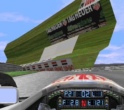
Here we see all 5 ribbons of the right track side folded up against the sky. We are interested in the TAG HEUER advert now which is mapped on r22. The values of the args are: a1=1; a2= 22; a3= 5; a4= 1219; a5= 1; a6= 32; a7= 16; a8= 35; a9= 10; a10= 0;
We see the offset given by a1, and the length of the mapping given by a9; We have set a3= 5 to see the repetition AND the (false) shift of the textures. If you look carefully you notice the texture is shifted to the left. In case you're in doubt you may want to check out sil_ads4.jam. This unwanted shift seems to depend on the rotation. If you have the same example with a8=3, there is no unwanted shift!
We also had doubled the "vertical resolution" by setting a6=32. So we actually mapped a texture with double the height than our selected texture 1219 has. And because the texture below 1219 in sil_ads4.jam does not have the same palettes, we have color distortions. However this seems to happen only in my system. In other systems the "vertical resolution" argument seems to work as expected.
Good to see is the vertical shift given by a7=16. It shifted the texture upwarts, so the upper border of TAG HEUER is cut.
After having been faced so much trouble we want to have a look at how we probably want to look it like.
Here we had set the following arguments (differences in bold): a1=1; a2= 22; a3= 10 (because we have a9=10); a4= 1219; a5= 2; a6= 16; a7= 0; a8= 35; a9= 10; a10= 0;
We see a perfect mapping of the texture 1219 twice (because of a5=2) on ribbon r22.
If the reader now thinks theory of relativity is easier to understand than this, i agree. I'd suggest to set the args as mentioned in the 2nd example and rotation along the values mentioned above to have an easy start. If you are brave then you may go on with your own experiments, to see and understand.
a8; we mentioned the "common" values 3, 19, 35, 51 etc. they are the same as in GP2. but in GP3 we also see different figures like e.g. 81, 113, 32769, 32801 on the verge locations 37-40.
a10: horizontal shift. this is e.g. used with texture ID 999 of ULine_64.jam in f1ct11.dat and others. with a10 you set up what clip of the long texture you would like to see mapped.
Thanks to all the people who brought pieces of information to me !
Vaino:
# 0xEA switches ribbons on.
arg1: offset
arg2: bitvalue
In arg2: bits from 0 to 9 are used to toggle ribbons.
Bit 0 means 1, bit 1 - 2 and so on... if someone is not used to these
bit-things.
As you see in TE, there are 4 ribbons to left and 4 to right (+ banks) (Cmd 0xEE). So total number of ribbon points is 10. Bit 0 switches the most left one and so on.
# 0xEB switches ribbons off.
Arguments are just the same as in 0xEA.
a1: offset
a2: ribbon bit value
woody:
in gp2, the 0xd9 (217) cmd turned on ribbons that would not show when the game was run w/ the detail turned down in the graphics menu. to have ribbons showing up no matter how reduced the detail in the options, you switched them on with 0xb9 (189) cmd instead.
in gp2 0xb0 (176) was used to turn off ribbons that were turned on by
both 0xb9 and 0xd9.
in gp3, ribbons turned on w/ 0xea (234) always show in low detail mode
(so its the old 0xb9, 189).
Those turned on by 0xec (236) recognise low-detail mode and so do not
display (so its the old 0xd9, 217).
so you would maybe expect for both 0xea and 0xec to have a common off
switch, like their equivalents did in gp2 (the old 0xb0, 176). However,
both 0xeb (235) and 0xed (237) are able to turn off ribbons
Looking at MPS spa, its apparant that 0xed is paired w/ 0xec (i.e.
it only turns off ribbons started by 0xec, not any started by 0xea)
Likewise 0xea is paired w/ 0xeb (as you can guess from the cmd number order)
so if this is right, there seems to be two different pairs on/off switch
systems.
what confused me is that, a 0xed cmd can successfully turn off scenery
started by a 0xea cmd, & 0xeb cmd can turn off ribbons started by 0xec.
and ribbons turned on by 0xec and then turned off by 0xeb are still recognised
as low detail (i.e. an 0xec/0xed pair)
my question was, has anyone found a positive difference between cmds
0xeb and 0xed?
(i'll remove all 0xed in spa & replace by 0xeb w/ same bit values,
& see what it looks like)
or as a relative newbie, have i got the gp2 cmd functions wrong?
BTW more precisely, by low detail mode I mean w/ the sliding switch set at greater than -2 (in auto detail mode) the ribbons turned on by 0xec do not show; those turned on by 0xea do show no matter what detail setting
p.s. i believe the ribbon bit values work the same for all 4 cmds 0xea - 0xed
a1: always zero (probably unused)
a2, a3: L5 dfc / z
a4, a5: L4 dfc / z
a6, a7: L3 dfc / z
a8, a9: L2 dfc / z
a10, a11: L1 dfc z
a12, a13: R1 dfc, z
a14, a15: R2 dfc, z
a16, a17: R3 dfc ,z
a18, a19: R4 dfc, z
a20, a21: R5 dfc ,z
Please see the following image:
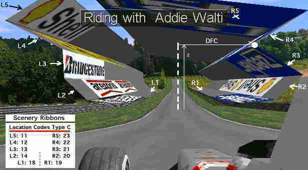
There is no more "Ribbons To The Right"-argument anymore as in 0xb8. We always have 5 ribbons on each side. So lets call them L5, L4, L3, L2, L1, then R1, R2, R3, R4, R5 as sketched in the image. On the panel in the image we also see the corresponding loc codes type C.
In the image we also see the "point" that defines R3. We see what is meant with DFC (distance from center) and z.
These are the Values in our example:
a1= 0;
a2= -1000; a3= 8000; a4= -1500; a5= 6000; a6= -1000; a7= 4000; a8=
-1000; a9= 2000; a10= -800; a11= 400;
a12= 800; a13= 400; a14= 1000; a15= 2000; a16= 600; a17= 4000; a18=
1000; a19= 6000; a20= -800 a21= 8000
Thanks goes to Woody for research and Fat Rat for labels.
[ .. 0xfe (definitely) not used in GP2]
0xff is said to mark the end of track data in the trackfile.
Index
0x80 Anchor Object
0x8a Track Markings Type A
0x8b Track Markings Type B
0xa8 Trigger Of Flag Men Waving At End Of Race
0xb2 Switch Borderlines Off
0xde Black Flag Area Left
0xdfBlack Flag Area Right
0x92 CC-Car Coaching Space
0x94 CC-Car Coaching Left
0x95 CC-Car Coaching Right
0x81 (129) View-Distance In Front
0x82 (130) View- Distance Behind
0xbe (190) Extended View-Distance In Front
0xbf (191) Extended View-Distance Behind
0xc5 (197) Define Far View
0xc6 (198) Far View Window
0x85 (133) Track Width Change
0xb4 (180) Track Width Change Left
0xb5 (181) Track Width Change Right
0x86 (134) Connect Pit Lane Start
0x87 (135) Connect Pit Lane End
0x88 (136) Pit Lane Cmd; Left Pits
0x89 (137) Pit Lane Cmd; Right Pits
0x96 (150) Speed Limiter On
0x97 (151) Speed Limiter Off
0x9b (155) Pit Lane Begin Offset
0x9e (158) Pit Lane End Length
0x9f (159) Pit Lane Fences Begin
0xa0 (160) Pit Lane Fences End
0xa1 (161) Pit Lane Entry; Join Right Pit Lane Fence
0xa2 (162) Pit Lane Entry; Join Left Pit Lane Fence
0xa3 Pit Lane Exit; Join Right Pit Lane Fence
0xa4 Pit Lane Exit; Join Left Pit Lane Fence
0xcf Show Pit Objects Through Pit Fence
0xd3 View Into Pit Lane Entrance
0xd4 View All Pit Lane From Entry
0xd5 View Into Pit Lane Exit
0xd6 View All Pit Lane From Exit
0xd7 Show Pit Scenery 1
0xd8 Show Pit Scenery 2
0xdb Switch Pits/Track Drawing Order
0x8e Left Kerbs Begin/Length
0x8f Right Kerbs Begin/Length
0xca Kerb-Type A
0xcb Kerb-Type B
0xe0 Kerb-Type A Adjust
0x98 Left Fence Height Change
0x99 Right Fence Height Change
0x9a Define Custom Fence Height
0xb8 Scenery Structure
0xaf Pair Of Swivel Arms
0xc0 Single Swivel Arm Left
0xc1 Single Swivel Arm Right
0xb0 Turn Ribbons/Banks Off
0xb9 Turn Ribbons/Banks On
0xd9 Turn Obj-Ribbons/Banks On
0xba 0xc2 0xc3 0xc4 Insert
Dummy Scenery Arms
0xda Silly Scenery Command
0xd0 Stabilize Textures
0xcc Adjust Horizon
0xbc Texture Mapping
0xc8 Scenery Texture Definition
0xbb Texture Mapping Light
0xc9 Set Colors In GP2-Palette
0xbd Light Source (Sun) Position
0xcd Adjust Shadow
0xad Track Banking
0xdd Weirdo Enabler
0x83 (131) 0x84 (132) 0x8c
(140) 0x8d (141)
0x90 (144) 0x91 (145) 0x93
(147) 0x9c (156) 0x9d (157
0xa5 (165) 0xa6 (166) 0xa7
(167) 0xa9 (169) 0xaa (170)
0xab (171) 0xac (172)
0xb1 (177) 0xb3 (179) 0xb6
(182) 0xb7 (183)
0xc7 (199) 0xce (206)
0xd1 (209) 0xd2 (210) 0xdc
(220)
TE
trackeditor program. PHTE: trackeditor of Paul Hoad. IHTE trackeditor
of Vaino Iso-Hannula
cmd
command
Offset Into Sector
A lot of cmds do have a parameter saying how far from the beginning
of the sector the cmd "happens". Sometimes this parameter is also refered
as "Start" or "Length Into Sector". The offset is not limited to the sector,
where the cmd is included. E.g. if the length of the sector is 3, the offset
could be e.g. 8, and so the action takes place in one of the next sectors.
?
sometimes you see a question mark in front of an argument descriptor
etc. (e.g. "?Location Code Type B"). This means there are indications for
this argument being what it is labeled, but its not really confirmed yet.
unk
unknown meaning (of a cmd or an argument)
unused
some arguments of cmds are set to 0 in the original tracks, and if
changing no effect ?is/was noticable. so this argument probably is unused.
(but who knows ?)
a7
argument 7 of a cmd; 7th argument of a cmd
t99
track-sector 99
p99
pit lane-sector 99
f1ct13 or Slot 13
original track 13 (GP2: Estoril); Slot 13
(all the numbers are just examples)
DFC (Distance from Centerline)
At first place the tracklayout is defined by its centerline. Lots of
arguments of cmds do refer to this centerline. Therefor a DFC value means
the distance of something perpendular to the track, to its centerline respectively.
There are several units for this value. The centerline is not always in
the middle of the road. This depends on the track width settings, that
can be asymmetrical.
DFS (Distance from Start)
Other arguments refer to the distance to the start/finish line. The
unit for this value is16 feet equals 4.8768m most of the time.
Ribbon
Several ribbons along the track on both sides do form the scenery.
Their shape is determined by track commands.
Sector
A sector is the smallest piece of a track in a trackfile. A sector
has constant curvature- and gradient change. Its length is measured in
a unit of 16 feet (4.8768m). In order to keep things simple and short,
I use the abbreviation t for track-sector and p for pit lane sector. So
t17 means track-sector 17 and p13 means pit lane sector 13.
Section
General term. Means some track-sectors in a row, sometimes with a common
property. E.g. uphill track-section means some track-sectors where there
is an uphill gradient.
Segment
GP2/3 internal unit that equals 1 track length unit (16ft; 4.8768m).
Verge
With verge we mean the space between the track and the fences. In the
early days of trackediting for GP2 this was also known as "bank". But order
to unify the terminology in track-editing with the terminology that is
used in GP2 we introduced the term Verge.
Fence
This is also an "official" GP2 term. It labels what formerly was know
as wall.
Bank
This labels the space between the fences and the first ribbons. Not
used anymore in GP3. There it does not make anymore sense to make a difference
between banks and ribbons.
The last few terms will now be visualized in a screenshot of the GP2 Jerez-track.
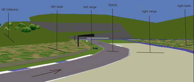
To visualize the meaning of the term "bank" i switched off all textures,
except those on the banks. In this screenshot on the right side of the
track we dont see the ribbons.
Location Code Type A (for cmd 0xcd)
A2 (GP2)
|
|
Location |
|
Location |
|
|
fence left |
|
fence right |
|
|
verge left |
|
verge right |
|
|
bank left |
|
bank right |
|
|
ribbon 1 |
|
ribbon 3 |
|
|
ribbon 2 |
|
ribbon 4 |
A3 (GP3)
|
|
Location |
|
Location |
|
|
fence left |
|
fence right |
|
|
verge left |
|
verge right |
|
|
ribbon L1 |
|
ribbon R1 |
|
|
ribbon L5 |
|
ribbon R2 |
|
|
ribbon L4 |
|
ribbon R3 |
|
|
ribbon L3 |
|
ribbon R4 |
|
|
ribbon L2 |
|
ribbon R5 |
B2 (GP2)
|
|
Location |
|
Location |
|
|
ribbon 1 |
|
ribbon 3 |
|
|
ribbon 2 |
|
ribbon 4 |
|
|
bank left |
|
bank right |
B3 (GP3)
|
|
Location |
|
Location |
|
|
ribbon (L5) |
|
ribbon (R2) |
|
|
ribbon (L4) |
|
ribbon (R3) |
|
|
ribbon (L3) |
|
ribbon (R4) |
|
|
ribbon (L2) |
|
ribbon (R5) |
|
|
ribbon L1 |
|
ribbon R1 |
Location Code B3 is for sure meant for the ribbons only. Left and Right
is for sure also. Same to L1 and R1. Thanks Rene Smit and Woody.
(codes for right ribbons not yet 100% sure which order)
Location Code Type C GP3
used for mapping textures most of all. several different lists on this:
|
|
Location |
|
Location |
|
|
?type A right kerbs outside |
|
?type A left kerbs outside |
|
|
fence right |
|
fence left |
|
|
ribbon L5 |
|
ribbon L4 |
|
|
ribbon L3 |
|
ribbon L2 |
|
|
|
||
|
|
?type A right kerbs inside |
|
?type A left kerbs inside |
|
|
|
||
|
|
ribbon L1 |
|
ribbon R1 |
|
|
ribbon R2 |
|
ribbon R3 |
|
|
ribbon R4 |
|
ribbon R5 |
|
|
|
||
|
|
?type B right kerbs outside |
|
?type B left kerbs outside |
|
|
?type B right kerbs inside |
|
?type B left kerbs inside |
|
|
|
||
|
|
right fence extension |
|
left fence extension |
|
|
|
||
|
|
left verge (see sketch) |
|
right verge (see sketch) |
|
|
|
Codes for Verges:
Type C Codes for the Ribbons:
|
|
11 |
23
|
R5
|
||||
|
|
12 |
22
|
R4
|
||||
|
|
13 |
21
|
R3
|
||||
|
|
14 |
20
|
R2
|
||||
|
|
18 | left side | |___________| |
right side
|
19
|
R1
|
see also screenshot at cmd 0xee
Location Code Type C GP2
|
|
Location |
|
Location |
|
|
fence right |
|
fence left |
|
|
verge right |
|
verge left |
|
|
road |
|
|
|
|
ribbon 1 |
|
ribbon 2 |
|
|
ribbon 3 |
|
ribbon 4 |
|
|
bank left |
|
bank right |
additional codes (as found by LD and Filou), not usable for cmd 0xbc (188) as far as I know
|
|
Location |
|
|
Type A Right Kerb Outside Part |
|
|
Type A Left Kerb Outside Part |
|
|
Type A Right Kerb Inside Part |
|
|
Type A Left Kerb Inside Part |
|
|
Road Floor at the Entry and Exit of Pitlane |
|
|
Type B Right Kerb Outside Part |
|
|
Type B Left Kerb Outside Part |
|
|
Type B Right Kerb Inside Part |
|
|
Type B Left Kerb Inside Part |
|
|
GP2 - as found by DC
|
|
Location |
|
Location |
|
|
grey road(no texture) |
|
? |
|
|
fences/walls |
|
? |
|
|
road |
|
|
|
|
verges |
|
banks |
|
|
all ribbons |
|
|
|
|
pitroad |
|
pitroad lines |
|
|
ribbon 1 |
|
ribbon 3 |
|
|
ribbon 2 |
|
ribbon 4 |
|
|
? |
|
? |
GP2
|
|
Description |
|
Description |
|
|
Default (All ribbons) |
|
|
|
|
Right verge |
|
Left verge |
|
|
Right fence |
|
Left fence |
|
|
Right bank |
|
Left bank |
Location Code F (not complete)
GP2
|
|
Description |
|
Description |
|
|
?Left fence |
|
?Right fence |
|
|
|
||
|
|
|
||
|
|
?Left verge |
|
|
|
|
|
||
|
|
|
||
|
|
Left bank |
|
Right bank |
|
|
|
||
|
|
|
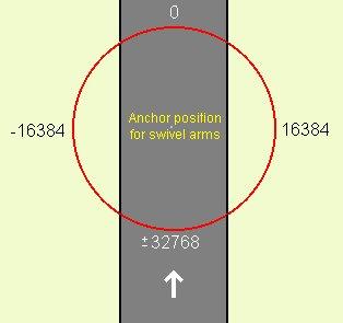
table with degrees and correspondant values (182.044 / degree):
| degrees (clockwise) | value (approx) | negative value |
| 0 | 0 | |
| 45 | 8192 | |
| 60 | 10923 | |
| 70 | 12740 | |
| 80 | 14560 | |
| 90 | 16384 | |
| 100 | 18200 | |
| 110 | 20020 | |
| 120 | 21840 | |
| 135 | 24576 | |
| 180 | 32768 | |
| 250 | 46410 | -19125 |
| 270 | 49152 | -16384 |
| 275 | 50176 | -15359 |
| 285 | 52224 | -13311 |
| 315 | 57344 | -8192 |
it doesnt matter whether you insert the positive or the negative representant of the value.
typical values (as can be found in f1ct14.dat):
11264, 12288, 13312, 13824, 14336, 15360, 16384, 17408, 18432, 19331,
19456, 21504, 24576
44030, 46080, 47104, 48128, 49152, 49213, 49315, 50176, 50183, 51200,
52224, 54272
Deler is a variable:
for pitlane values, deler=32768/20
for track values, deler=32768/30
TrackWidth(Meters)=
(TrackWidthGP2/deler)*4.87;
FenceWidth(Meters)=( (FenceWidthGP2*(1024/30))*TrackWidthGP2/1000)/deler*4.87
I have tested these formulas and they are highly accurate."
a1 most of the times is the offset, that means the length into the sector, where a cmd has to happen. Numbers 1..100 could be also a length (x16ft), or a transition length. Sometimes its not x16ft, but maybe inch ...
Figures 16384, 49152 or similar could represent an angle, see compass-chapter for details.
Sometimes a value is said to be always 0 and if you have a look at the original tracks it is indeed always 0. the question is: HAS it to be always 0, or is it maybe a hidden gadget ? (we never know :)
UNSIGNED vs. INTEGER
Big positive numbers, e.g. 65438, also could be a low negative number:
in computer programming everything is stored in bits and bytes. A typical
storing-unit is two-bytes (16bit), also called word (in a 16bit environement).
In such a word you can either store a number 0..65535, that means 2^16
(2 power 16), such a number is called UNSIGNED or CARDINAL. Or it can be
stored as a so called INTEGER number, -32768 .. +32767. But its the same
two-bytes, its just a matter of interpretation. That means a certain number,
say 65000, could be interpreted as UNSIGNED 65000, or as INTEGER -535;
same two-bytes, different interpretation. So if an argument of a cmd has
typical values 0..1000 and 64535 .. 65535, this actually smells like INTEGER:
0..1000, -1 .. -1000. Here the calculation: 0..32767 its the same INTEGER
and UNSIGNED; 65535 downto 32768 you have to interpret as -1 downto -32768,
calculation: integer:= unsigned-65536.
UNSIGNED vs. BIT
The same two-word could also be interpreted as a bunch of bits. So
if there are typical values 1, 2, 4, 8 or 16, etc. This could have to be
interpreted bitwise. The first bit from the right is 1, the second 2 the
third 4, the fourth 8, the fifth 2^5 (2 power 5), etc. e.g. have a look
at a2 of cmd 0xcd, this looks like a typical two-word that has to be interpreted
bitwise.
general
Some arguments have to be interpreted as direction, where you have
to do some value-to-angle transformation, see e.g. a8 of cmd 0xbc. You
may want to look for cmds that have similar arguments with similar typical
values. etc. its chasing ...
Last but not least
If you find something, please do notify me. I will collect and integrate
it in this library ...
More Tech Info (for unk- chasers)
by Rene Smit
Ok, I've created a table of the passes, including the commands that do nothing (#):
1, 2 or 3: only this pass
*: all passes
#: no effect
-: invalid command
|
|
|
|
|
|
|
|
|
|
|
|
|
|
|
|
|
|
|
|
|
|
|
|
|
|
|
|
|
|
|
|
|
|
|
|
|
|
|
|
|
|
|
|
|
|
|
|
|
|
|
|
|
|
|
|
|
|
|
|
|
|
|
|
|
|
|
|
|
|
|
|
|
|
|
|
|
|
|
|
|
|
|
|
|
|
|
|
|
|
|
|
|
|
|
|
|
|
|
|
|
|
|
|
|
|
|
|
|
|
|
|
|
|
|
|
|
|
|
|
|
|
|
|
|
|
|
|
|
|
|
|
|
|
|
|
|
|
|
|
|
|
|
|
|
|
|
|
|
|
|
|
|
|
|
|
|
|
|
|
|
|
|
|
|
|
|
|
|
|
|
|
|
|
|
|
|
|
|
|
|
|
|
|
|
|
|
|
|
|
|
|
|
|
|
|
|
|
|
|
At load time the track gets "compiled" into an internal format. This
compiler passes several times. Not all commands are processed in the same
pass.
-nov 9, 2000; loc code A for gp3;
-nov 4, 2000; cmd 0xe1/e2 correct loc codes now; thanks john!
-nov 4, 2000; loc code B for gp3 corrected (right ribbon codes reversed!)
-sep 24, 2000: 0xe9; a10 explained. important not at
-sep 15, 2000: 0xb7; removed extension by woody, as it (according to
woody) prooved to be wrong.
-sep 12, 2000: revised description of "dummy scenery arm"-cmd 0xba/c2/c3/c4
by woody
-sep 10, 2000: fixed loc code 3B (thanks woody!)
-sep 4, 2000: cmd 0xc2-c4, 0xb4 continue scenery; cmd 0xca define kerb
profile
-aug 30, 2000: more rework; "long list"
-aug 29, 2000: rework some here and there; loc code type C
-aug 22, 2000; rework cmd 0xee
-aug 19, 2000; rework cmd 0xe9
-aug 17, 2000; extend cmd 0xe9
-aug 15, 2000: rework every here and there
(Aug 3, 2000)
-initial version; completely reviewd from v2.8 for GP2